AcuCT Flex CT Installation Guide
AcuCT Flex Installation Guide Overview
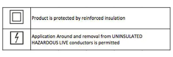
Key Symbols

AcuCT Flex Warnings
Warning: Disconnect power supply before making electrical connections.
Warning: Current Transformers (CT’s) should be installed by trained electrician or technician.
Warning: The secondary circuit of a CT should not be opened when current is flowing through the primary circuit.
Installation Steps for AcuCT Flex CTs
- Connect leads to the CT terminals on meter as detailed in the wiring diagram of the meter’s datasheet. The white leads of the CT are the positive wire and the brown lead is the negative wire.
- Open the coil by pulling apart the black connector of the CT.
- Install the CT around the conductor to be measured. Verify the CT is installed with the CT facing the same direction as the current flow direction indicated by the arrow on the black connector.
- Re-attach the coil together.
- Repeat Steps 1 through 4 if using more than one CT.
- Ensure that the CT connected to meter is around the correct phase/line voltage.
Caution:
The primary conductor of the current transformer must provide double insulation.
This equipment is intended to be used as a current transformer.
If the equipment is used in a manner not specified by the manufacturer, the protection provided by the equipment may be impaired. Important: The secondary winding shall not be left open when the primary side of equipment is installed on live system.
No cleaning is required.
Environmental:
The CT is rated for indoor use only. The altitude is up to 2000 meters. Ambient Temperature range is -20°C to 40°C. Maximum relative humidity is 85% for temperature up to 31°C decreasing linearly to 50% relative humidity at 40°C. Rated pollution degree 2
Functional Check: When necessary, short the secondary output lead and measure the current or voltage from the secondary lead. The output should be full range according to rating, when the primary side is rated current.
Electrical Rating:
Voltage rating: 600V, CAT III, 50-60Hz Current rating: 5A-5000A depends on the model of the CT
Related Articles
Acuvim II Installation Guide
Acuvim II Installation Guide Overview We walk through the installation of the Acuvim II power and energy meter in a number of configurations. Voltage and Current Connection The Acuvim II can be installed using some of the common installation methods ...Change CT Direction from Meter Settings 1312
AcuRev 1310 – Changing the CT Direction from the Meter Settings This document provides users with a walkthrough on how to change the direction of the CT through the meters settings. This setting change is performed from the AcuRev 1310 series meter ...AcuRev 1310 - How to use Wiring Check
Wiring Check The AcuRev 1312 meter supports a built-in wiring check function, this allows users to identify what the actual error is on the meter. This check uses the voltage and current phase angles to determine if there is a wiring issue. If the ...Create Calculated Meter for DI Counter on AcuRev 2100
AcuCloud – Creating Calculated Meter for DI Counter on AcuRev 2100 This document provides users with a walkthrough on how to create a calculated meter on AcuCloud to represent the DI counter for the AcuRev 2100 meter. Users will need to have an ...